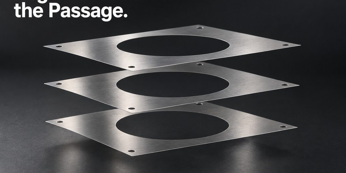
Every layer can pass inspection on its own and still leave a restricted passage when the layers are stacked. The cause may be the relationship between the openings, not the size of any one opening.
Alignment in a layered metal assembly starts with a shared locating scheme. Relate the functional pattern to the assembly datums, keep layer orientation unambiguous and allow the joining process to be part of the tolerance discussion. Inspecting each sheet independently is only one part of the job.

The overlap becomes the passage
Imagine two thin plates with the same circular opening. Place them exactly together and the openings coincide. Shift one sideways and the common clear area shrinks. No hole has become smaller; the available passage has changed because the layers moved.
The same reasoning applies to slots, ports and patterned spacer layers. A tolerance on the outer rectangle does not control a passage unless that rectangle is also the feature used to locate the assembly. The datum scheme should reflect how the parts are actually positioned.
Registration features need a job of their own
Locating holes should remain accessible for the assembly operation. An apparently convenient hole may become covered by another layer. A symmetric pattern can also allow a part to be flipped or rotated into a position that looks correct at its perimeter.
An asymmetric locating detail can make orientation visible. The complete locating arrangement still needs appropriate clearance; simply adding more close-fitting pins can overconstrain a stack. The objective is repeatable positioning, not the largest possible number of locating points.
Joining can hide a good alignment—or disturb it
The stack seen before joining is not necessarily the final geometry. The assembly process may introduce movement or deformation, and solid lands must remain continuous wherever the design relies on them. This is why a successful flat-sheet dimensional report should travel with an assembly validation plan.
ZEISS’s September 14, 2026 VersaXRM 5 Insight announcement describes combined X-ray microscopy and microCT. Such methods can help investigate hidden internal geometry when the material, feature size and available resolution permit. They do not automatically replace functional flow or leak testing.
A better drawing package shows the stack
Alongside each layer drawing, include one assembly view showing orientation, locating features and the intended open passage. Identify the layer revisions together. A supplier can then review pattern-to-datum relationships rather than guessing how several otherwise correct sheets are meant to meet.
When discussing etched layers with XINKETCHING, start with that assembly view. The most useful tolerance is the one that protects the passage the finished stack actually needs.
Related engineering reading: metal etching process and DFM guide; thin thermal layers; microhole measurement.
References: ZEISS, VersaXRM 5 Insight announcement (2026-09-14).

- What Can a Pilot Lot Actually Prove About Etched-Part Repeatability? - October 9, 2026
- How Much Open Area Remains After an Acoustic Mesh Is Assembled? - October 8, 2026
- How Do You Compare Etched Prototypes Without Losing Track of the Design? - October 7, 2026