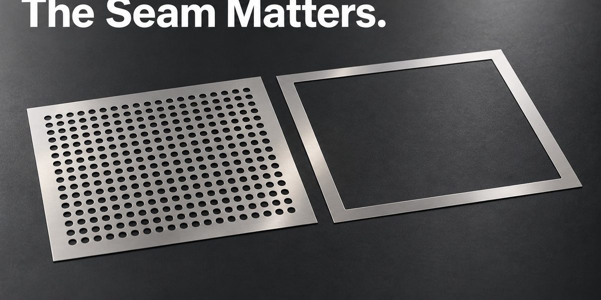
Making the vent holes smaller will not repair an electrically poor seam around the lid. An enclosure is a system of conductive surfaces, openings and contacts. Improving one feature can leave the main leakage path untouched.
For an etched EMI shield, aperture geometry and electrical continuity at the joints need to be considered together. Hole size alone cannot establish a shielding rating. Frequency, source location, enclosure geometry and assembly condition all affect the result.

Three places where the design can change
| Feature | What the metal drawing controls | What the assembly must establish |
|---|---|---|
| Vent pattern | Opening shape, spacing and metal remaining between holes | Cooling and shielding behavior in the enclosure |
| Lid perimeter | Flange geometry and contact locations | Reliable conductive contact around the seam |
| Finish | Specified treatment and masked regions | Compatibility with mating surfaces and service conditions |
A long slot and a compact hole with the same area need not behave alike electromagnetically. Open area is a useful mechanical or ventilation description, but it is not a complete shielding specification. The longest opening dimension and the relevant frequencies deserve attention.
The contact path continues through the seam
Parker Chomerics’ shielding guidance explains the role of conductive gasketing in maintaining current continuity across a joint. In a formed sheet-metal cover, the equivalent design question is whether the intended contact exists after tolerances, fastening and surface treatments are included.
A flange that looks continuous in CAD may touch its mating frame at only a few places. A coating selected for appearance may be inappropriate where electrical contact is required. Those are assembly details with electrical consequences, not secondary cosmetic choices.
Where etching helps
Etching can produce repeated openings and complex flat outlines in thin metal. Forming, finishing and assembly remain separate parts of the manufacturing route. A photo-etched blank can be dimensionally correct without demonstrating the shielding effectiveness of the finished enclosure.
Siemens’ September 11, 2026 discussion of frequency-dependent parasitic extraction is a related reminder that an electrical design cannot always be reduced to its DC behavior. It is background for this engineering question, not evidence about an etched shield or a specific product.
For a XINKETCHING drawing review, identify the ventilation region and the electrical contact regions separately. That allows the thin-metal pattern to be discussed without losing the seam that completes the shield. Keep the final EMI requirement with the assembled enclosure test, where those features operate together.
Related engineering reading: metal etching process and DFM guide; microhole measurement.
References: Parker Chomerics, Theory of Shielding and Gasketing (accessed 2026-09-16); Siemens, From DC to High Frequency: Parasitic Extraction in Simcenter Flux (2026-09-11).

- What Can a Pilot Lot Actually Prove About Etched-Part Repeatability? - October 9, 2026
- How Much Open Area Remains After an Acoustic Mesh Is Assembled? - October 8, 2026
- How Do You Compare Etched Prototypes Without Losing Track of the Design? - October 7, 2026