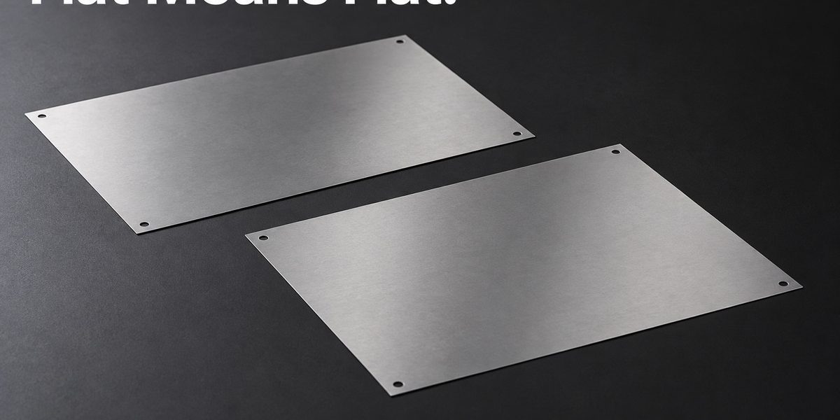
A thin plate can lie flat under a clamp and spring up when the clamp is removed. Both observations can be real. They describe different conditions.
Before comparing flatness measurements for an etched part, decide whether the requirement applies to the free part or to the part under a defined assembly restraint. The fixture, support points and applied force belong to that definition. Otherwise, a supplier and a customer can produce convincing numbers for different versions of the same problem.

The fixture can change the thing being measured
A broad solid plate and a fine perforated sheet respond differently to support. Removing metal changes how the sheet resists bending. A probe force or clamp that has little visible effect on the solid plate may disturb a slender ligament in the patterned part.
This does not make contact measurement inherently unsuitable. It means the contact location and force need to suit the component. Optical measurement avoids probe contact, but it still measures the shape created by the support fixture. A non-contact sensor cannot undo a plate flattened by the fixture beneath it.
Choose the question before choosing the instrument
ZEISS’s September 10, 2026 O-INSPECT webinar discusses combining optical and tactile measurement. For thin etched components, that is a useful reminder that different features can need different methods. An outline, a mounting-hole position and a surface shape do not necessarily need the same measurement approach.
For a free-state requirement, the support should hold the part without intentionally forcing it into the desired shape. For an assembly-state requirement, reproduce the specified mounting condition. Record enough detail that a second inspection station can recreate it.
A repeat measurement can reveal the hidden variable
Measure a sample, remove it, reload it and measure it again. If the result changes substantially, investigate positioning and support before drawing conclusions about manufacturing variation. Leaving the same part untouched and taking another reading tests only part of the measurement process.
Also separate surface marks from surface form. A photograph of a bright reflected line may make a small slope look dramatic, but it is not a calibrated flatness result. Conversely, a uniform-looking finish does not establish that the part will seat against its mating surface.
Put the condition on the drawing
A short note describing orientation, support and restraint can be more valuable than another decimal place. Include the measurement stage if the part is later formed, coated or bonded. Those operations can change the shape that matters in service.
For a XINKETCHING thin-sheet project, share the mounting condition with the part geometry. That connects the flatness requirement to the assembly instead of leaving both teams to invent a fixture after the samples arrive.
Related engineering reading: metal etching process and DFM guide; microhole measurement.
References: ZEISS, Optical and CMM Inspection with O-INSPECT webinar (2026-09-10).

- What Can a Pilot Lot Actually Prove About Etched-Part Repeatability? - October 9, 2026
- How Much Open Area Remains After an Acoustic Mesh Is Assembled? - October 8, 2026
- How Do You Compare Etched Prototypes Without Losing Track of the Design? - October 7, 2026