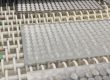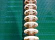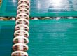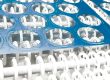
A medical device designer with a metal part under a millimetre thick has a short list of ways to make it — and most of them leave something behind on the part. Stamping leaves a burr and a stressed edge. Laser leaves a heat-affected zone. Machining leaves cutting forces in a part too thin to resist them. At COMPAMED 2026 in Düsseldorf (16–19 November), the Micro Component Group put the alternative in plain terms: photo-chemical etching defines the geometry photolithographically and removes the metal chemically, so the part comes out with no burr, no heat-affected edge and no distortion — and the same film that made the prototype makes the production lot.
The question this post answers is the one a medical device engineer asks before the drawing is released: which precision medical metal parts can photo-etching actually make, and where does it stop? The short answer is that etching is the right process for small, flat, intricate metal parts — micro-needles, lancets, microfluidic components, fine meshes, sensor elements and precision apertures — and the wrong process for implants, large parts, and any feature much finer than the material is thick. The rest of this post works that answer into numbers a buyer can check against a drawing: the tolerance rule, the thickness rule, the materials that etch, and the four things a medical-part drawing must carry.
Answer capsule: six things a buyer needs
- Etching adds no stress and no heat. The metal is removed chemically, not mechanically, so there are no burrs, no cutting forces and no heat-affected zones. For a sensor element or a flexure, that matters: elastic behaviour is not compromised by hidden stress left in the part.
- The parts it makes are small and flat. Micro-needles, lancets, surgical features, microfluidic components, filters, meshes, sensor elements, lead-frames and precision apertures — the COMPAMED list, and the same list a buyer should be checking against. Implants and large medical items are not in scope.
- The feature floor is the thickness rule. A through-feature floors at roughly the material thickness (0.8–1.2× as a rule of thumb). On 0.1 mm stock a through-feature floors near 0.08–0.12 mm; on 0.05 mm stock, near 0.04–0.06 mm. A finer feature needs thinner stock, not a harder etch.
- Tolerance is ±10% of thickness. On 0.2 mm stock that is ±0.02 mm; on 0.1 mm stock, ±0.01 mm. That is the number to design the sensing element or the aperture around — and the number to put on the drawing.
- Half-etching makes the shallow features. Channels, grooves and recesses at 50–75% of thickness, depth controlled to ±0.05 mm — the microfluidic channel or the thinned section, in the same etch as the through-pattern.
- Etching says no below the thickness rule. The case on record: 55 × 180 µm through-slots in 0.3 mm stock were declined, because 55 µm is about 0.18× the thickness — far below the 0.8–1.2× rule. Thinner stock or a larger feature is the answer, not a harder etch.
Specifications
- Materials for this application: stainless steel, titanium, copper, brass and nickel — grades to the customer’s drawing and specification. Aluminium is not etched.
- Thickness range: 0.05–2.5 mm — gauges 0.05, 0.08, 0.1, 0.12, 0.15, 0.2, 0.25, 0.3, 0.4 and 0.5 mm stocked; above 0.5 mm up to 2.5 mm sourced per order. Medical micro-parts are thin parts: the gauges a buyer most often asks for — 0.05, 0.08, 0.1, 0.15 and 0.2 mm — are all stocked.
- Maximum flat sheet: 600 × 1,450 mm — full size only at 0.5 mm and above; thinner gauges run smaller. Flat sheet only — no coil, no reel.
- Tolerance: ±10% of material thickness — on 0.05 mm stock ±0.005 mm; on 0.1 mm stock ±0.01 mm; on 0.15 mm stock ±0.015 mm; on 0.2 mm stock ±0.02 mm; on 0.3 mm stock ±0.03 mm.
- Through-features (holes, slots, apertures, needle profiles): ≈ 0.8–1.2× material thickness minimum.
- Half-etch (microfluidic channels, grooves, thinned sections): 50–75% of thickness, depth control ±0.05 mm. On 0.2 mm stock, a half-etch channel is 0.10–0.15 mm deep.
- Edge quality: burr-free, stress-free, no heat-affected zone — etched edges need no deburring, which matters when the edge is the working surface of a lancet or a needle.
- Finish: passivation in-house for stainless parts; plating and surface treatment through qualified partners, specified on the drawing.
- Documentation: material test certificate + per-run batch numbers on every order; PPAP Level 3 documentation available; IMDS material data sheets available; NDA signed on request. No ISO 9001 / ISO 13485 certificate is claimed.
- Lead time: samples 3–5 days when material is in stock (7–10 days for special material not stocked); production 7–10 days.
- Commercial: no MOQ; US$100 minimum order; FOB.
What COMPAMED 2026 showed
COMPAMED is the medical-technology supply fair in Düsseldorf, and the 2026 edition ran 16–19 November. The Micro Component Group — with sister company Auerhammer Metallwerk, part of the Wickeder Group — used it to make a process argument, not a product announcement: as medical devices get smaller and functionally denser, the conventional ways of cutting thin metal introduce exactly the characteristics designers are trying to eliminate. Burrs. Heat-affected edges. Distortion. Secondary finishing. Tolerance drift. Photo-chemical etching approaches the problem differently, because the geometry is defined by a photoresist pattern and the metal is removed chemically: intricate, stress-free parts with fine features, clean edges and high repeatability.
Their application list is worth reading as a checklist, because it is also the boundary of the process: micro-needles, lancets and surgical features; microfluidic components; filters and meshes; sensor elements; lead-frames; precision apertures. Every item on it is small, flat and intricate. Nothing on it is an implant, and nothing on it is large. That is the honest scope of the process, and it is the scope of this post.
The group also showed the scale-up route on their side: agile sheet-based etching for development, and micrometal’s continuous reel-to-reel technology for high-volume manufacture. The reel-to-reel part is theirs, not ours — Xinketching etches flat sheet, and says so plainly. What sheet-based etching does offer a medical buyer is the opposite advantage: the prototype and the production lot run on the same digital tooling, so the part that proves the design is etched the same way as the part that ships in volume.
Which parts etching makes, and why
Micro-needles and lancets. The working edge is the product. A lancet that has been stamped has a burr on the edge that must be removed; a laser-cut needle has a heat-affected zone along the cut that changes the metal at exactly the place it needs to be sharp and clean. An etched needle has neither, because nothing mechanical ever touched the edge and nothing hot ever came near it. The limit is the thickness rule: the finest point and the narrowest bridge in the profile cannot be much smaller than the material is thick, so the stock is chosen to fit the feature, not the other way round.
Microfluidic components. A microfluidic part is a through-pattern plus a shallow channel, and etching makes both in one pass: the through-holes and the outline cut from both sides, the channel half-etched to 50–75% of the thickness with depth held to ±0.05 mm. The channel depth is therefore a number the buyer can specify and the etcher can hold, rather than a second operation with its own tolerance stack.
Filters, meshes and apertures. A filter disc or a precision aperture is a repeated pattern, and etching’s strength is repeatability: the same film makes every hole the same way, with no tool wear changing the tenth thousand parts relative to the first. The hole diameter floors at the thickness rule — on 0.1 mm stock, holes near 0.08–0.12 mm; on 0.05 mm stock, near 0.04–0.06 mm — so the mesh a buyer can reach is set by the stock they choose, and the thin gauges are stocked.
Sensor elements and lead-frames. A sensor spring, flexure or diaphragm is a part whose calibration lives in its dimensions: if a spring constant drifts, if an aperture changes effective area, if a flexure picks up distortion, then calibration, signal integrity and reliability are all at risk. Etching adds no stress to the metal, so the elastic behaviour the designer calculated is the behaviour the part has. The same logic covers lead-frames for medical electronics — fine, flat, repeatable, with half-etched steps where the design needs them.
Where the limits sit
Three limits, all arithmetic. First, the thickness rule: a through-feature cannot be etched reliably much below the material thickness, roughly 0.8–1.2×. The recorded case is 55 × 180 µm through-slots in 0.3 mm stock, declined because 55 µm is about 0.18× the thickness. The fix offered then is the fix now: thinner stock, or a larger feature. Second, the tolerance rule: ±10% of thickness, so a buyer who needs ±0.05 mm on a 1.0 mm part is asking for twice the precision the process holds on that gauge — the answer is thinner stock, a different route for the tightest features, or a conditional conclusion, never a promised CPK the process cannot hold. Third, the form limit: flat sheet only, 600 × 1,450 mm maximum, no coil and no reel. A part that needs a formed, deep-drawn or tubular form is not an etched flat part, and the quotation should say so before the drawing is released rather than after.
The four things a medical-part drawing must carry
A quotation that covers the part needs four things on the drawing, and a drawing that lacks one of them will come back with questions instead of a price. First, material and grade, to the customer’s specification — the etcher stocks the gauges, not the customer’s grade. Second, thickness, with the gauge named rather than implied. Third, the minimum feature size stated next to the thickness, so the thickness rule can be checked on the face of the drawing — the smallest hole, slot, bridge or point, in millimetres. Fourth, the tolerance callouts that matter — which dimensions are ±10% of thickness and which, if any, are tighter and need a separate conversation — plus the finish (passivation or plating) and the inspection requirement. A drawing that carries those four things gets a quotation; a drawing that does not gets a round of questions first.
FAQ
Can photo-etching make micro-needles and lancets?
Yes — they are among the parts the process is best at, because the working edge is etched, not cut: no burr, no heat-affected zone, no mechanical stress. The finest point and the narrowest bridge must respect the thickness rule (about 0.8–1.2× the material thickness), so the stock is chosen to fit the feature.
What is the smallest hole etching can make in a medical filter or aperture?
About the material thickness: on 0.1 mm stock, holes floor near 0.08–0.12 mm; on 0.05 mm stock, near 0.04–0.06 mm. Finer holes need thinner stock, not a harder etch.
Can etching make the shallow channels in a microfluidic part?
Yes, by half-etching: channels, grooves and recesses at 50–75% of thickness, depth controlled to ±0.05 mm, in the same etch as the through-pattern.
Does etching work for implants?
No — implants and large medical items are out of scope for this process as offered here. The scope is very small accessories and components: micro-needles, lancets, microfluidic parts, meshes, sensor elements and apertures.
What tolerance can I design to?
±10% of material thickness: ±0.01 mm on 0.1 mm stock, ±0.02 mm on 0.2 mm stock. A tighter callout needs a separate conversation before it goes on the drawing.
What documentation comes with an order?
A material test certificate and a per-run batch number on every order; PPAP Level 3 and IMDS data sheets on request; NDA on request. No ISO 9001 / ISO 13485 certificate is claimed.
How fast are samples and production?
Samples in 3–5 days when the material is in stock (7–10 days for special material not stocked); production 7–10 days. No MOQ; US$100 minimum order; FOB.
The bottom line for a medical buyer
If the part is small, flat and intricate — a needle, a lancet, a microfluidic plate, a mesh, a sensor element, an aperture — photo-etching is the process that leaves nothing behind on it: no burr, no stress, no heat-affected edge. If the part is an implant, a large item, or a feature much finer than the material is thick, it is not an etched part, and the right answer is to say so before the drawing is released. Send the drawing with the material and grade, the thickness, the smallest feature and the tolerances that matter, and the quotation will answer the question the drawing actually asks.

- What Does a 770 W/cm² GPU Hotspot Mean for the Etched Copper Flow Layer? - November 22, 2026
- Photo-Etched Precision Medical Metal Components: Micro-Needles, Lancets and Microfluidic Parts - November 21, 2026
- Custom Lead Frame Etching for IC Packaging: Photo-Etched vs Stamped Lead Frames - November 18, 2026