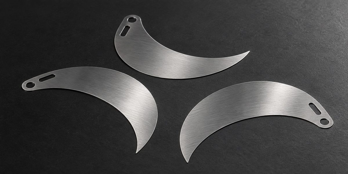
An aperture blade can match its drawing and still drag against the blade beside it. In a small iris, the moving surfaces, pivot clearance and finish matter as much as the outline.
Both photo etching and laser cutting can be candidates for thin metal aperture blades. Etching is attractive when several fine features can be patterned together without mechanical cutting forces. Laser cutting offers a direct digital cutting route. The useful comparison is between finished, coated blades running in the intended mechanism—not just two clean-looking blanks.

A current example is a reason to compare, not to assume
Apple’s September 9, 2026 announcement explicitly describes six laser-cut blades in its variable-aperture camera. It would be incorrect to describe those blades as etched. For a different optical design, however, that manufacturing choice opens a worthwhile question: which edge, thickness and motion requirements decide the process?
The optical edge and the clearance edge do different work
The edge defining the aperture controls the light opening. Another edge may only need to clear the housing. Giving both the same demanding tolerance adds work without necessarily improving the optical result. Pivot holes and drive slots add another relationship: their position controls how the blade moves, not merely where it sits in a dimensional report.
Etched edges have a profile through the sheet thickness. Laser-cut edges have their own process-dependent surface condition. Rather than specifying only an outline tolerance, relate the critical edge to its role: light control, contact or clearance. That gives a supplier a reason for each requirement.
Leave room for the finish
A coating changes the finished surface and can consume clearance at an opening. Consider a hole coated on its internal wall: even a uniform layer reduces the available diameter. The relevant acceptance condition is therefore the finished component when that hole runs on a pivot.
Black appearance alone also says little about friction or optical behavior. The finish must suit the optical and mechanical requirements, and the blade stack must still move after that finish is applied. A trial that uses bare blades cannot settle a coating-related contact problem.
Compare the route through assembly
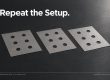
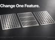
A small prototype comparison can hold alloy, thickness, finish and housing constant while changing the cutting route. Compare the finished aperture motion and the critical geometry. If several other variables change too, a better result will not tell you which change caused it.
When discussing a blade with XINKETCHING, mark the optical edge, pivot and contact surfaces on the same drawing. Those three details make a process comparison far more useful than a request for the tightest possible tolerance everywhere.
Related engineering reading: metal etching process and DFM guide; thin thermal layers.
References: Apple, iPhone 18 Pro and iPhone 18 Pro Max announcement (2026-09-09); Precision Micro, Chemical Etching Technical Guidelines (accessed 2026-09-16).

- What Can a Pilot Lot Actually Prove About Etched-Part Repeatability? - October 9, 2026
- How Much Open Area Remains After an Acoustic Mesh Is Assembled? - October 8, 2026
- How Do You Compare Etched Prototypes Without Losing Track of the Design? - October 7, 2026