The plates inside a PEM electrolyzer must carry current, move water in, move gas out, and hold a stack together under pressure — in an acidic, oxygen-evolving environment that attacks most metals. A 2026 paper in the Latvian Journal of Physics and Technical Sciences tested two full PEM electrolyzer stacks fitted with nano-coated titanium porous transport layers (PTLs) and bipolar plates. A US patent application funded by the Department of Energy (US20260331534A1) proposes redesigning the bipolar plate’s flow field so gas can get out from under the lands. Both point at the same component — the etched titanium flow-field plate. Xinketching is a photochemical etching manufacturer in Dongguan, China, producing flat etched metal parts since 2005. We etch titanium, but we do not supply the stacks in these papers, and we do not apply the coatings they test.
Answer capsule: six things a buyer needs
- We etch titanium. Titanium is one of the five metals we photo-etch — stainless steel, titanium, copper, brass and nickel. We do not etch aluminium.
- The etched part is the bipolar plate’s flow field, not the PTL. Porous transport layers are sintered titanium felt or powder. They are not photo-etched, and no etcher can make one. The bipolar plate — the flat plate carrying the channels that feed water in and gas out — is the part etching makes.
- Titanium earns its place on chemistry. The anode side of a PEM electrolyzer runs in a strongly acidic, oxygen-evolving environment. Grade 2 titanium (commercially pure, ≥ 99.2% Ti per ASTM B265, tensile strength ≥ 345 MPa, density ≈ 4.51 g/cm³) survives it where stainless steel does not.
- The flow field is a half-etch. Channels run 50–75% of the sheet thickness, depth control ±0.05 mm. On 0.3 mm stock a 60% channel is 0.18 mm deep; the remaining web keeps the plate stiff and flat.
- Tolerance is ±10% of thickness. On 0.2 mm stock that is ±0.02 mm; on 0.3 mm stock, ±0.03 mm; on 0.5 mm stock, ±0.05 mm.
- The feature floor is the thickness rule. A through-feature floors at roughly the material thickness (0.8–1.2×). A 0.20 mm hole in 0.3 mm stock is a case we declined — the same rule governs pin-type lands and fine channels: finer features need thinner stock, not a harder etch.
Specifications
- Materials: stainless steel, titanium, copper, brass, nickel (we do not etch aluminium)
- Titanium grades etched: commercially pure Grades 1 and 2 and alloy Grade 5 (Ti-6Al-4V); Grade 2 is the usual choice for electrolyzer plates
- Thickness range: 0.05–2.5 mm — gauges 0.05, 0.08, 0.1, 0.12, 0.15, 0.2, 0.25, 0.3, 0.4 and 0.5 mm stocked; above 0.5 mm up to 2.5 mm sourced per order
- Maximum flat sheet: 600 × 1,450 mm — full size only at 0.5 mm and above; thinner gauges run smaller
- Tolerance: ±10% of material thickness
- Half-etch (channels): 50–75% of thickness, depth control ±0.05 mm
- Through-features: ≈ 0.8–1.2× material thickness minimum (0.20 mm hole in 0.3 mm stock declined)
- Form: flat sheets only — no coil, no reel; we do not diffusion-bond or braze assemblies
- Finish: passivation available; we do NOT apply platinum, iridium oxide, titanium nitride or other electrolyzer/fuel-cell coatings
- Lead time: samples 3–5 days when material is in stock (7–10 days for special material not stocked); production 7–10 days
- Commercial: no MOQ; US$100 minimum order; FOB; material test certificate + per-run batch numbers on every order
What a bipolar plate does, and which part is etched
A PEM electrolyzer stack is a sandwich. The patent’s background lists the layers in order: end plates, current collectors, bipolar plates, porous transport layers, and catalyst layers on both sides, with a solid polymer electrolyte membrane in the middle. Water splits at the anode into oxygen, protons and electrons; protons cross the membrane and become hydrogen at the cathode. The bipolar plate sits between two cells and does four jobs: it conducts current from one cell to the next, distributes water evenly through its flow field, collects the gas that evolves, and holds the stack together under clamping pressure.
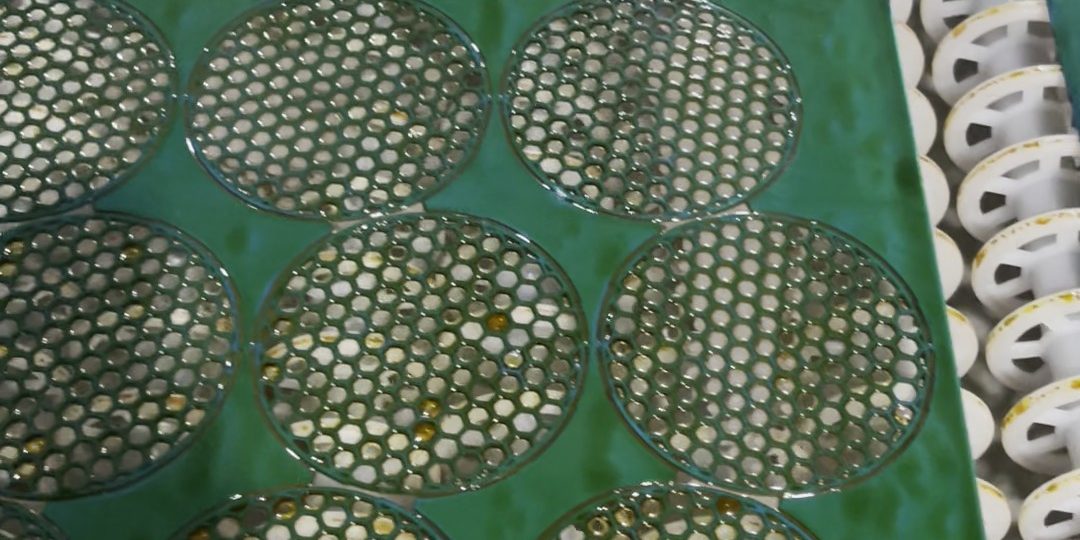
The flow field is the pattern of channels and lands cut into the plate’s face. The lands press against the PTL and carry current; the channels carry water in and gas out. Photo etching suits this part because the whole pattern is cut in one pass, with no mechanical stress and no heat-affected zone, so a large flat plate stays flat — and a design revision is new artwork rather than new tooling. Flow-field layouts are still moving — parallel, serpentine, interdigitated, pin-type — and a buyer still iterating geometry does not want a new stamping die at every revision. Our liquid-cooling cold-plate DFM guide covers the same etched-channel discipline for electronics cooling — a different product, but the same logic of channel depth, pitch and flatness.
Now the boundary that matters most. The porous transport layer is a porous body — sintered titanium felt, sintered powder, foam or mesh — that moves water, gas, heat and current between the bipolar plate and the catalyst layer while supporting the membrane. A PTL is made by sintering, not by etching; no photochemical etch can produce a sintered felt. The bipolar plate is a solid flat plate with a flow field etched or machined into its face — this is the etched part. HydroMatx’s catalogue lists titanium bipolar plates in grades GR1, GR2 and GR5 with “machined or etched flow fields” for PEM fuel cells and PEM and AEM electrolyzers. The 2026 Latvian paper tested coated PTLs and bipolar plates as a pair, and its results describe the pair — so send the etcher the plate, not the PTL.
What the 2026 paper actually tested
The paper (Backurs et al., Latvian Journal of Physics and Technical Sciences, 2026, No. 1, pp. 38–50) is an industrial-scale evaluation, not a laboratory cell test: two full PEM electrolyzer stacks, built with nano-coated titanium PTLs and bipolar plates, run in a real hydrogen generator system. Stack 0316/44 used coated PTLs and coated bipolar plates; Stack 0317/44 used coated PTLs only. Both stacks were conditioned for 40 hours at 15 bar, then tested at 0.6 and 1.2 A/cm². At 150 A the voltages were 89.8 V (0316/44) and 88.9 V (0317/44); at 300 A, 99.3 V and 102.8 V. Gas purity stayed within safe limits: residual oxygen in hydrogen from 14 ppm to 31 ppm, hydrogen crossover below 0.7%. In the SIRIO 1000 system at 300 A the combined voltages were 106.0 V and 104.0 V, and average power consumption was 5.75 kW/Nm³ — about 10–20% higher than standard industrial stacks.
Those are the paper’s results for its coated stack pair, not a specification any plate supplier can promise: a stack test measures the whole system — coatings, PTL, membrane, assembly — and a supplier who quotes stack voltage or gas purity as their own performance is claiming someone else’s test. We quote plate geometry, tolerance and material.
What the DOE patent changes about flow-field design
US patent application US20260331534A1, funded by the US Department of Energy (Grants EE0008426 and EE0008423), attacks one failure mode: gas accumulating under the lands. The micropores in the PTL are often blocked by the lands of the bipolar-plate flow field, so transport is impeded under the solid land area; gas accumulation there is much larger than under the channel area, causing severe ohmic and mass-transport losses, especially at high current density.
The patent’s answer is a pin-type flow field: discrete lands — in some embodiments, substantially circular contact pillars — in a staggered pattern, so the PTL’s pores sit substantially unobstructed by the lands. Against conventional parallel or serpentine designs, which the patent says can obstruct a substantial portion of the underlying PTL (a porosity of 0.5 or less), a pin-type flow field aligned with the PTL can reach an effective porosity above about 0.88. A representative test used a pin-type flow field with a micro-patterned diffusion layer with 200 µm pores, and the pin-type design outperformed the parallel design at low and high flow rates. A titanium nitride coating is mentioned in the patent’s figures — a coating step, not an etching step, and not ours. The lesson is about the drawing: wide lands cover PTL pores; discrete pins leave them open. Settle that geometry with the stack designer first.
Why titanium, and which grade
The anode side of a PEM electrolyzer is hostile to metal: strongly acidic, oxygen-evolving, wet, and under pressure. Titanium’s defence is a thin, self-healing titanium dioxide film that resists oxidising acids, chlorides and seawater without pitting or crevice attack in most cases — which is why Titanium Valley calls Grade 2 the default material wherever stainless steels fail on chlorides. The boundary from the same source: hot, strongly reducing acids such as concentrated hydrochloric or sulfuric acid break the film, and those services need a different grade family or an explicit engineering review.
Grade 2 is the usual choice: commercially pure titanium (≥ 99.2% Ti per ASTM B265), minimum tensile strength 345 MPa, yield strength 275–450 MPa, minimum elongation 20%, density approximately 4.51 g/cm³. Grade 1 is softer and more formable; Grade 5 (Ti-6Al-4V) is stronger and is the aerospace alloy. HydroMatx lists all three — GR1, GR2 and GR5 — for titanium bipolar plates, and Titanium Valley puts PEM electrolyzer bipolar plates at 0.1–0.5 mm in Grade 2, with end plates and supports at 0.5–1.0 mm, the flow fields etched and then given a noble-metal catalyst coating. That coating is the stack builder’s step, applied after etching. A drawing that says only “titanium” leaves the grade and the certificate unanswered. Our guide to etching titanium — when the weight or the chemistry earns it covers the grade decision in more detail. Titanium’s most public recent test is the etched plate under Samsung’s Galaxy Z Fold 8 display — our Fold 8 post explains what its lattice does.
How to specify an etched titanium flow-field plate: the four drawing items
A quotation we can price in one pass needs four things on the drawing. Everything else — quantity, delivery, packaging — is commercial and can follow.
- Material and grade. State the alloy and the standard: “Titanium Grade 2 to ASTM B265” or “Ti-6Al-4V (Grade 5)”. A material test certificate with heat number is our standard on every order. If the plate will be coated after etching, say so — the coating supplier will have surface requirements. Our passivation and plating guide explains what finish to specify and where coating responsibility sits.
- Thickness and channel depth. State the sheet thickness and the channel depth as a half-etch callout. Our half-etch runs 50–75% of thickness with depth control of ±0.05 mm: on 0.3 mm stock a 60% channel is 0.18 mm deep; on 0.5 mm stock it is 0.30 mm deep. The remaining web keeps the plate stiff under clamping pressure, so do not specify deeper than 75%. Full 600 × 1,450 mm size is available only at 0.5 mm and above; thinner gauges run smaller, so a large-area plate in 0.2 mm stock may need to be split or re-gauged.
- Channel and land geometry, with pitch. State the channel width, the land width (or pin diameter and pitch for a pin-type field), and the inlet/outlet openings. Then check the feature floor: a through-feature needs roughly the material thickness (0.8–1.2×). A 0.20 mm hole in 0.3 mm stock is a real case we declined, and the same rule governs fine pins and narrow lands — if the design needs 0.15 mm pins, the stock should be 0.15 mm or thinner, not 0.3 mm. Pitch tolerance follows the same ±10% rule — see our photo-etching tolerances guide for worked examples.
- Outline, flatness and finish. State the outline dimensions and their tolerance, the edge condition, and the finish: passivation is available and is the usual finish for a titanium plate that will be coated downstream. State flatness as a requirement the drawing actually carries, plus the quantity and revision letter so a re-order cuts the same artwork. Our buyer’s guide to photo-etched parts sets out the full drawing checklist behind these four items.
A drawing with those four items gets a priced quotation without a round of questions. A drawing with only an outline and a material name gets a questionnaire back — the slowest way to buy a plate.
Ordering: samples first, then production
The sensible route is a small sample run against the drawing, measured and fitted in the stack, then a production order once the geometry is confirmed. Samples run in 3–5 days when the material is in stock (7–10 days for a special material not stocked); production runs in 7–10 days. There is no minimum order quantity, and the minimum order charge is US$100, on FOB terms. Every order carries a material test certificate and per-run batch numbers, so a plate can be traced to its material heat and etch run.
FAQ
Is the porous transport layer (PTL) photo-etched?
No. PTLs are sintered titanium felt or powder (also made as foam or mesh). No photochemical etch can make one. The etched part in a PEM electrolyzer stack is the bipolar plate’s flow field.
Do you apply the platinum, iridium oxide or titanium nitride coating?
No. We etch the titanium plate and can passivate it. Coatings for electrolyzer and fuel-cell service are applied by a coating supplier after etching. Tell us on the drawing if the plate will be coated downstream.
Which titanium grade should I specify for a bipolar plate?
Grade 2 (commercially pure, ASTM B265) is the usual choice: ≥ 99.2% Ti, tensile strength ≥ 345 MPa, density ≈ 4.51 g/cm³. Grade 1 is softer and more formable; Grade 5 (Ti-6Al-4V) is stronger. State the grade and the standard on the drawing.
How deep can the flow channels be etched?
Channels are a half-etch: 50–75% of the sheet thickness, depth control ±0.05 mm. On 0.3 mm stock a 60% channel is 0.18 mm deep; on 0.5 mm stock it is 0.30 mm deep. Do not specify deeper than 75% — the remaining web keeps the plate stiff under stack clamping pressure.
What is the smallest channel or pin I can specify?
Roughly the material thickness. Through-features floor at about 0.8–1.2× the stock thickness — a 0.20 mm hole in 0.3 mm stock is a case we declined. If the design needs 0.15 mm pins, use 0.15 mm stock or thinner. Tolerance on every dimension is ±10% of thickness.
How large can one plate be, and can it be aluminium?
Our maximum flat sheet is 600 × 1,450 mm, full size only at 0.5 mm and above — thinner gauges run smaller. Flat sheets only: no coil, no reel. And no, we do not etch aluminium. Our five etched metals are stainless steel, titanium, copper, brass and nickel.
What do the 2026 paper’s voltage and gas-purity figures mean for my order?
They are the paper’s results for its own coated stack pair (Backurs et al., 2026): 89.8 V and 88.9 V at 150 A, 99.3 V and 102.8 V at 300 A, residual oxygen in hydrogen of 14–31 ppm, hydrogen crossover below 0.7%, average power consumption 5.75 kW/Nm³. They describe a complete coated stack, not a plate. We quote plate geometry, tolerance and material.

- What Does a 770 W/cm² GPU Hotspot Mean for the Etched Copper Flow Layer? - November 22, 2026
- Photo-Etched Precision Medical Metal Components: Micro-Needles, Lancets and Microfluidic Parts - November 21, 2026
- Custom Lead Frame Etching for IC Packaging: Photo-Etched vs Stamped Lead Frames - November 18, 2026