| Thickness (mm) | Tolerance (±mm) |
|---|---|
| 0.10 mm | ±0.015 |
| 0.25 mm | ±0.025 |
| 0.50 mm | ±0.050 |
[/vc_column_text][/vc_column][/vc_row]
Mastering Precision: The Ultimate Guide to Chemical Etching Tolerances for Industrial Design

Introduction: Why Tolerance is the Heart of Chemical Etching
In the realm of high-precision manufacturing, Photo Chemical Etching (PCE)—also known as Chemical Milling or Photo Chemical Machining (PCM)—has emerged as the gold standard for producing complex metal parts without the thermal stress of laser cutting or the mechanical burrs of stamping. However, for engineers and procurement professionals, the most critical question remains: What are the achievable tolerances?
Understanding the relationship between material thickness and dimensional accuracy is not just a technical necessity; it is a cost-saving strategy. In this guide, we will delve into the physics of lateral undercut, the industry-standard rule, and how to optimize your designs for maximum yield.
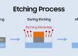
The Physics of the Etch: Understanding Undercut
To understand tolerance, one must first understand how chemical etching works. Unlike a CNC drill that moves vertically, chemical etching is a “subtractive” process where an acid solution (usually ferric chloride) dissolves unprotected metal.
As the acid eats downward into the metal, it also inevitably eats sideways under the photoresist mask. This phenomenon is known as Undercut.
The “Etch Factor” is the ratio of downward etch to lateral etch. Because this process is fluid and dynamic, the thicker the material, the longer it must stay in the etching machine, and the more “room” there is for slight variations in the lateral etch rate. This is precisely why tolerances are expressed as a percentage of thickness.
The Golden Rule: Explained
For the vast majority of industrial applications using stainless steel, copper, or brass, the standard tolerance is calculated as ±10% of the material thickness.
Example A: For a 0.1mm foil, your expected tolerance is ±0.01mm.
Example B: For a 1.0mm plate, your expected tolerance expands to ±0.1mm.
While advanced facilities can occasionally push these limits to ±8%, designing with the 10% rule ensures that your parts can be manufactured consistently across different batches with high yield rates.
Factors That Influence Dimensional Accuracy
Beyond simple thickness, several variables can “tighten” or “loosen” your tolerance window:
Material Composition: Stainless steel 302 and 304 are highly predictable. In contrast, certain “exotic” alloys or tempered aluminum may react more aggressively to the etchant, requiring a slightly wider tolerance margin.
Double-Sided vs. Single-Sided Etching: By etching from both sides simultaneously, the acid meets in the middle of the material thickness. This effectively halves the “etch time” for any single point, significantly improving the precision of the vertical walls and reducing the undercut profile.
Part Geometry: A part with extremely dense features (many small holes close together) may experience “localized etchant depletion,” where the acid becomes saturated with metal ions in tight spaces. This can lead to slightly different tolerances on the interior of a part compared to its outer edges.
Information Gain: Practical Design Tips for Engineers
Most online guides simply tell you the tolerance. To provide true Information Gain, we offer these “insider” optimization tips rarely found in standard textbooks:
The “Corner Radii” Secret: In chemical etching, internal corners will always have a radius approximately equal to the material thickness. If your design requires a sharp 90-degree internal corner, etching may not be the right choice—or you must design “over-etch” relief notches.
Grain Direction Matters: In very thin foils, the rolling direction of the metal can slightly affect the etch rate. For ultra-precision medical meshes, aligning critical dimensions with the metal grain can improve consistency.
The “Land” vs. “Space” Ratio: To maintain structural integrity during the process, the “land” (the metal remaining between two etched features) should ideally be at least 1.2x the thickness. If the land is too thin, the photoresist may peel off prematurely.
Cost vs. Precision: The Procurement Perspective
Why not always ask for ±5% tolerance? In chemical etching, tighter tolerances require:
Slower conveyor speeds (reduced throughput).
Frequent chemistry titrations and adjustments.
Higher inspection costs (AOI – Automated Optical Inspection).
By utilizing our Etching Tolerance Calculator above, you can determine if your project fits within standard “Cost-Effective” zones or if it enters the “Premium Precision” zone.
Conclusion: Partnering with the Right Manufacturer
Chemical etching is as much an art as it is a science. While the math gives us a baseline, the experience of the technician managing the acid temperature, pressure, and concentration is what ultimately delivers a perfect part.
When sending out an RFQ (Request for Quote), always provide your material grade and thickness first. Use the rule as your design foundation, and you will find that chemical etching offers a level of complexity and speed that no other manufacturing process can match.

- Etching Cost Calculator - June 14, 2026
- Surface Area Calculator - May 24, 2026
- Etch Rate Calculator - May 24, 2026